A few days ago I visited my parents. The main purpose was to ‘deposit’ my new Lecroy WaveAce 224 DSO. I bought it as a gift for myself, but I haven’t fulfilled all criteria to receive the gift yet. Therefore my parents are ‘guarding’ it for me until I’m allowed to have it. As Lecroy were offering a promotional sale on these, I just had to buy it right now.
I happened to see a pretty simple nitelite my mom likes to use. It comes with a base unit and a glass sphere resembling the planet earth on top of that. It only had a blue LED, and a pretty inefficient one as well. It was pulling 80mA and wasn’t any bright at all. The upgraded ‘thing’ now comes with an RGB LED and an ATmega168 microcontroller as the brains. The metal cap now works as a capacitive touch sensor.
Image may be NSFW.
Clik here to view.
As you can see in the video, as soon as you touch the base it changes color. In normal mode it slowly fades through all colors. When touched, it shows the delay time used for the fading encoded in red and blue. If it’s more on the red side the delay is large, if it’s on the blue side the delay is small. The longer you touch it, the more the delay is changed. I used an uint8_t variable to hold it, so it automatically wraps around to zero once it gets larger than 255.
Here’s a look at the somewhat messy innards:
Image may be NSFW.
Clik here to view.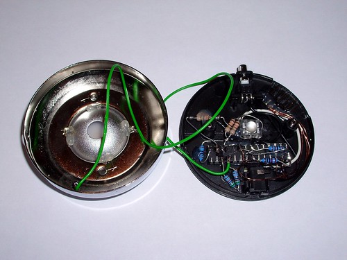
The metal cap to the left connects to two pins of the ATmega168 microcontroller. Together with 2x 510kΩ resistors it forms a voltage divider. The cap has a small capacitance against ‘ground’ that can be charged through the resistors. The code of the CapSense library measures the time it takes until the ‘sense pin’ changes its state from LOW to HIGH (RC-time measurement). By moving your hand closer to the metal base the capacitance is increased. In case the power supply is not grounded (wall wart), the measurement is somewhat limited, as the ground reference is missing. The difference is huge if you do the same measurement when connecting it to your PC (which is grounded). That’s why I had to set the threshold to 2 to get any result. When connected to properly grounded PC, the values reported by the code are magnitudes higher. It might have helped to install a copper ground plane, but that wasn’t possible. Together with the metal cap it would have approximated a parallel plate capacitor.
Closeup of the important parts:
Image may be NSFW.
Clik here to view.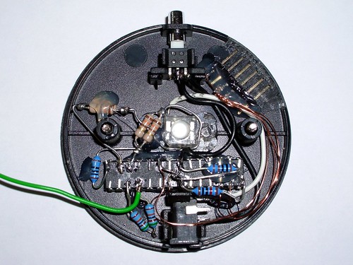
The 1kΩ resistor glued to the ATmega168’s belly is used to bring the wall wart’s voltage down to a safe value. It’s a cheap one labeled to provide 3.5V. When loaded with the old blue LED it supplied 3.8V at 80mA. With no load it spits out 6V, which would kill the microcontroller. The resistor pulls about 5mA out of it which brings it down to about 5 volts, which is safe enough. The 10kΩ resistor is used as a pull-up for the RESET pin, 100Ω go to the red LED and the parallel pairs of 130Ω are used for blue and green.
Here’s the pretty simple code. It requires the Arduino CapSense library by Paul Badger.
A few words of caution:
Please make sure you’ve flashed a bootloader to the chip AND verified that it actually works BEFORE you start the solder job. I had flashed a bootloader, but as it turned out it was the wrong one. ARGH ARGH ARGH. I can recommend the ‘ATmegaBOOT_168_lilypad.hex’ one with a long enough wait phase. The other ones don’t give you enough time for manual upload. Fuse settings for internal RC oscillator: LFUSE:0xE2 – HFUSE:0xDD – EFUSE:0x00
As the chip is mounted belly up, it is VERY useful to draw a mirrored diagram of all the pins you’ll need to use + their function. If you don’t do this, you’re bound to make mistakes. Trust me on this.